This post will start the beginning of PAMSTAMP, the software for online simulation and such. It is especially suited for use of mechanical engineers.
🔧 SECTION: ESI PAM-STAMP Overview
💡 What is PAM-STAMP?
PAM-STAMP is a full-scale simulation solution made for accurate sheet metal forming. It is an advanced simulation software by ESI Group for everything related to sheet metal forming. It’s used by engineers to digitally prototype the stamping process — so instead of wasting money and time building real-world prototypes, you simulate them with accurate predictions. It’s engineered to handle everything you need to digitally simulate, analyze, and optimize the stamping process from start to finish.
This software helps tooling engineers, designers, and production planners by predicting every single step in the manufacturing line — before you even build a prototype. It basically eliminates the guesswork and waste that come with traditional trial-and-error.
One cool thing: the simulation results from PAM-STAMP can be directly used in ESI’s Virtual Performance Solution, which means your final product simulations (like crash analysis) can use parts “as they’re really made,” not just how they’re designed.

🧬 Developed Over 25 Years
This software isn’t some quick project. It’s the result of 25+ years of continuous development, built in collaboration with both industry experts and academic researchers. It now covers all types of forming processes — whether you’re using cold, warm, or hot forming methods — and supports all kinds of materials like:
- Steel (including AHSS and UHSS)
- Aluminum
- Titanium
- Magnesium alloys
⚡ Super-Fast Computation
The latest PAM-STAMP release has a brand new algorithm that uses an explicit computation strategy. The results? It’s now up to 3x faster than older versions. And thanks to its seamless integration with any CAD/CAE tool, setup time can be cut by up to 90%!
🧰 Other Features & Integration
PAM-STAMP comes bundled with several powerful modules:
- CAD cleanup
- Cost estimation
- Material nesting optimization
- Die surface design
- Visual-Environment platform
- CATIA V5 compatibility
🔁 Processes Covered by PAM-STAMP
Here’s a comprehensive list of what PAM-STAMP can handle:
- Virtual prototyping of full stamping chains
- Cold, warm, and hot forming
- Hot forming with partial/full hardening
- Tailored blanks, patch blanks, rolled and welded blanks
- Drawing and deep drawing
- Crash forming
- Trimming
- Bending and flanging (including CAM integration)
- Hemming (manual and roll-based)
- Die spotting
- Tube and sheet hydroforming
- Ironing
- Coining
- Stretch and flex forming
- Spin and roll forming
- Aqua drawing
- Rubber pad and superplastic forming
- Closure marriage simulation with joining kinematics
- Progressive, line, and transfer dies
- End-to-end virtual prototyping — including integration with joining and performance simulation
🔑 Technical Strengths of PAM-STAMP
Here’s why PAM-STAMP is a go-to solution in the simulation world:
- Clean, accurate results with no trade-offs
- Built-in CAD topology check and repair
- Instant material cost estimation
- Modern die face design using B-Spline geometry
- Auto die starter for instant geometry generation
- Fast simulation link with CAD tools
- Full control over blank and drawbead sections
- Support for shell and solid blank modeling
- Automatic mesh refinement for simulation accuracy + speed
- Can handle welded patch blanks and blank-to-blank contact
- Advanced material and friction modeling, with dependencies like:
- Pressure
- Speed
- Temperature
- Custom variables
🛠️ Smart Process Setup & Simulation
- Guided workflows for standard users (less to configure)
- Stamp toolkit for power users (create your own macros)
- Full customization of objects, attributes, and parameters via attribute trees
- Intelligent data checking
- Seamless simulation management — from single PC to entire networks
- Precise contact models that prevent tool penetration (even with millions of elements)
- Advanced formulations for springback and cosmetic defect accuracy
- Temperature-aware forming (hot/warm/cold) with support for phase transformations
- Triple-speed simulation with no artificial mass scaling — unique in the market!
- Handles fine details like:
- Wrinkle folding
- Springback under gravity
- Cosmetic defects (skid lines, sinks, shock lines, etc.)
🔄 Automated Post-Processing
- Automatically checks:
- Draw-in
- Splits
- Wrinkles
- Press-force
- Springback
- Cosmetic defects
- Handles ironing simulation for through-thickness effects
- Blank shape and trim line optimization
- Fully automated springback compensation, including:
- Gravity effects
- Mounting conditions
- Bottoming
🎛️ Included Product Modules
Note: Some modules mentioned below have their own user guides and aren’t fully covered in this document, but they are part of the ecosystem.
🔹 Visual-CAD Clean
Tool for checking and repairing imported CAD models (explained more in the next section).
🔹 Visual-Quoting
A tool for quick material cost estimates using flattening + nesting methods.
🔹 Visual-DIEMAKER
Design die faces on a CAD-independent platform and export tool/process data.
🔹 PAM-DIEMAKER for CATIA V5
Same as above, but works directly inside CATIA V5.
🔹 PAM-AUTOSTAMP
Also called just PAM-STAMP. It’s the core process setup + simulation tool, including optimization and compensation.
🔹 PAM-INVERSE
A one-step solver that gives you a quick look at blank shape estimation and early feasibility checks.
🔹 DeltaMESH
Automated meshing engine used during simulation setup.
🧹 Topology Check, Cleanup and Repair – Get Your CAD Ready for Simulation
Before you run a simulation, your CAD data needs to be clean and perfect — no broken edges, missing surfaces, or overlaps. That’s where this step comes in.
In PAM-STAMP, topology cleanup is handled through a tool called Visual-CAD Clean. CAD models often come in all kinds of formats, and transferring them to simulation tools can cause all sorts of glitches. Visual-CAD Clean is your cleanup crew.
💥 Why Topology Check Matters
Not all CAD and simulation requirements match 1:1. During data transfer between CAD systems and simulation environments, data loss or corruption can easily occur.
Things like:
- Gaps between surfaces
- Cracks in the geometry
- Duplicated surfaces
- Holes or bad trims
These errors can mess up your simulation or make meshing impossible.
🔧 What Visual-CAD Clean Does
It automatically scans your model for issues and helps you fix them fast, either automatically or manually. For example:
- Red lines appear to mark problems (see image below)
- After cleanup, those red lines disappear, showing a clean model
You can:
- Fix surfaces automatically
- Fill holes manually or with autofill tools
- Delete bad geometry
- Re-trim sloppy surfaces
- Join disconnected surfaces
Once cleaned, you get a green topology which means your model is meshing-ready.

📦 Key Features of Topology Repair
Let’s break down all the tools and tricks Visual-CAD Clean gives you to prepare your model:
🔍 Automatic Tools:
- Detect and delete duplicate surfaces
- Fill holes automatically
- Auto-trim messy or over-trimmed geometry
- Generate repair surfaces that are simulation-friendly
🧰 Manual Tools:
- Delete unwanted geometry
- Split/trim surfaces as needed
- Add blend, sweep, or revolve surfaces
- Offset or transform geometry
- Create missing surfaces between opposing edges
🎯 Smart Navigation:
- Step-by-step error detection
- Add problems to a “collector”
- Use auto-clean to fix everything in one go
🖼️ Visual Tools You Get
- View and zoom in on gap issues
- Delete faulty surfaces
- Automatically fill gaps
- Recheck with topology view (red = error, green = good)

⚙️ Surface Repair Options (You Can Mix and Match)
- Coincident surface check
- Strip overlapping regions
- Detect and patch small holes
- Autofill complex gaps with clean surface creation
- Customize surface behavior (flat, swept, revolved, offset)
- Use transformations to fix alignment
🔄 DeltaMESH Integration
When your cleaned CAD data goes into DeltaMESH (the automatic meshing engine used by PAM-STAMP), it runs another layer of topology checking during the import process.
You can customize how this works in the DeltaMESH tab under Custom Options — adjusting things like geometry handling, import parameters, and joining behaviors.
So even if a bad surface sneaks past your cleanup, DeltaMESH adds a second defense line.
💰 Visual Quoting – Material Cost Estimation in Seconds
Need to estimate material costs before you even finish the design? That’s exactly what Visual-Quoting in PAM-STAMP is made for.
This tool works independently of any CAD platform, thanks to its base in Visual-Environment. That means whether you use CATIA, SolidWorks, or any other CAD tool, Visual-Quoting can still help.
🏁 What is Visual-Quoting?
Visual-Quoting is an ultra-fast utility that helps engineers and manufacturers estimate how much material a sheet metal part will use — and how much it’ll cost.
It can:
- Flatten out a part in seconds (aka “blank development”)
- Nest it efficiently into a coil layout
- Tell you the minimum possible material price
All of this happens super early in the design stage — when you’re just testing ideas.
⚙️ Key Features at a Glance
- 🧩 Blank Unfolding – Automatically flattens the 3D geometry of a part to calculate material use
- 🧮 Nesting & Price Estimation – Optimally fits the flattened blanks into a metal coil to find best layout
- 📊 Thinning, Strains & FLD – Gives you forming limit diagram (FLD) and strain estimates from a one-step simulation
🔍 Let’s Break Down the Details
✨ Fast Geometry Import
- Load solid or surface models
- Tool can auto-extract the top, mid, or bottom surface (depending on what’s relevant)
- It even handles undercut regions during flattening — which many other tools fail to do
🧠 Flatten with Inverse Solver
- Instead of just “guessing” the blank shape, Visual-Quoting uses a fast and accurate inverse solver
- This makes blank prediction much more realistic, especially for complex parts
🧾 Integrated Material Database
- Choose from a wide variety of real-world material data
- No need to hunt for specs online or dig through PDFs
🧱 Nesting Configuration Options
- Nest single parts or multiple parts together
- Handle different production setups like:
- One-up layout
- Two-up layout
- Transfer die arrangements
- The tool tries out different combinations to maximize material usage
🖱️ One-Click Reporting
Once everything’s calculated:
- The software can generate a report automatically
- Includes details like:
- Material used
- Cost per part
- Nesting layout
- FLD/thinning visuals
This makes it super useful for quotes, budget planning, or client discussions.
🖼️ Visual Summary
- First, you see a flattened blank from your 3D part
- Then, it shows how it fits inside a sheet coil
- You get a full workflow view
- Final result includes detailed reporting and visual validation
🧰 Die Face Design & Tool/Process Data Definition
If you’ve ever wished designing dies could be easier, more automated, and better integrated with simulation — this is your section. In PAM-STAMP, die face design can be done in two ways:
- Using PAM-DIEMAKER for CATIA V5
- Or using Visual-DIEMAKER on a CAD-independent platform
Both tools are built to prepare geometry for simulation — with minimal manual effort.


💡 Traditional Way vs New Way
Before, when you imported CAD models of tools into PAM-STAMP, they were just dumb geometry. You had to manually add:
- Blank data
- Drawbeads
- Process parameters
This took tons of time.
Now, with PAM-DIEMAKER or Visual-DIEMAKER, you can design dies and set parameters up front, then send everything to PAM-STAMP with just a few clicks.
🧭 Two Workflow Options
📁 1. When you only have part geometry
Let’s say you only have the part’s CAD model — no die yet.
The workflow is:
- Prepare the part (smooth outlines, close holes, etc.)
- Design the binder
- Add the addendum (the surface between part and binder)
- Export to PAM-STAMP with all data included
🛠️ 2. When the full die description is available
In this case, you already have punch + binder geometry and just need to define:
- Drawbeads
- Split regions (punch/binder)
- Process parameters
Then export directly into the PAM-STAMP simulation environment.
🧩 Key Features of the Die Design Tools
- Die Face Workbench – A full suite of tools to go from final part geometry to a complete draw die
- Tipping Tool – Automatically finds the best orientation to minimize draw depth and detect undercuts
- Single or Double Part Support – With or without symmetry
- Part Prep Functions – Fix holes, smooth outlines, etc.
- Binder & Addendum Creation – Auto-create these critical surfaces
- Trim Line Development – Define where the flanging happens
- One-Click Export – Send all data (tools, blank, process, material) to PAM-STAMP for simulation
🚀 Massive Time Saver
Starting with PAM-STAMP 2012.2, if your die face was designed using ESI’s die design tools, the software can import way more information — like:
- Drawbeads
- Punch/binder splits
- Material
- Process steps
That means setting up a stamping simulation for a draw die can now take just 20% of the time it used to take manually.
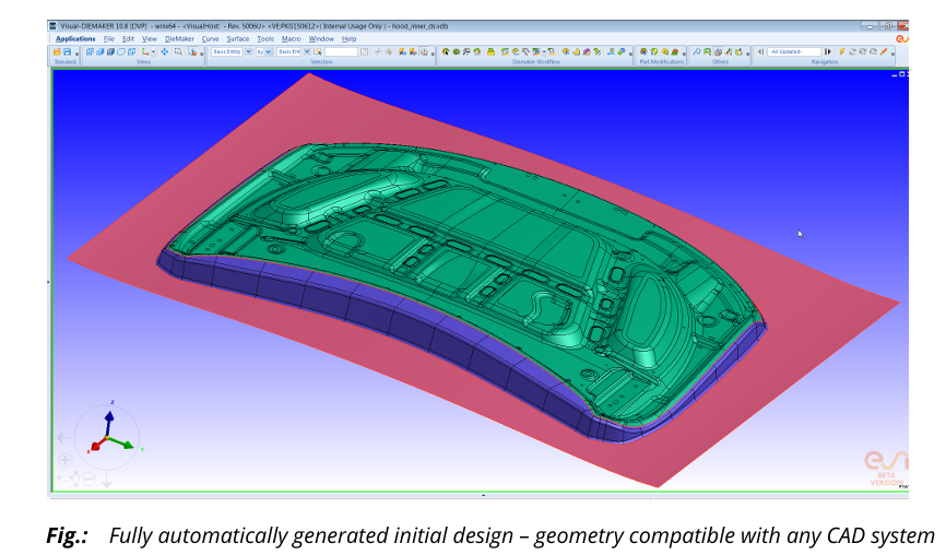
⚙️ Die Starter – Auto-Generated Die Design + Optimization
The Die Starter comes built into Visual-DIEMAKER, and it’s all about speed. It creates a full die face, including:
- The binder
- The addendum
- The drawbead centerlines
It only needs the part geometry and a basic outline — and it does the rest automatically.


💡 What It Does
The Die Starter:
- Reads the prepared part geometry
- Generates complete die surfaces
- Creates clean, simulation-ready geometry (binder, addendum, etc.)
- Works with CAD files or even meshed parts (like Nastran files)
The final output is real geometry, not just a mesh — meaning you can:
- Import it into any CAD system
- Or send it directly into PAM-STAMP via the Quick-Link feature in Visual-DIEMAKER
🧠 Smart Optimization Engine
After creating the initial die design, the Die Starter also runs an optional optimization step, using a custom-built solver.
It automatically:
- Adjusts the binder shape
- Tweaks wall angles
- Smooths out punch radii
- Calibrates drawbead forces
🎯 The goal? To minimize material usage while meeting design specs.
🖥️ Simulation Environment – Your Command Center in PAM-STAMP
The simulation environment in PAM-STAMP is known as PAM-AUTOSTAMP. You might also hear people call it PAM-STAMP (they’re the same thing in this context).
This is the main space where everything — meshing, simulation setup, solver configuration, post-processing — takes place. It’s like the cockpit for your entire forming simulation journey.
🧩 A Unified Interface for All Tasks
All the different simulation modules, like:
- Meshing
- Setup
- Results/post-processing
…share a common GUI in PAM-AUTOSTAMP. So no need to switch apps or environments — it’s all in one place.
You can also switch between modules easily, and the system guides you when it makes sense (e.g., when setup is incomplete).
🎯 Process-Specific Contexts
PAM-STAMP gives you dedicated “contexts” for specific processes, like:
- Stamping
- Roll hemming
- Hot forming
- Tube bending
Each context comes with customized settings that match the selected process. When you choose one, PAM-STAMP adjusts the interface and default configurations to match that manufacturing method.
🧱 DeltaMESH Integration
DeltaMESH is PAM-STAMP’s automatic meshing engine, and it’s deeply built into the simulation environment.
🔁 What It Does:
- Automatically meshes tool surfaces and curves when you import them
- Stores all imported tools and meshes in a project database
- Lets you either:
- Transfer meshes straight to the Setup module
- Or keep them in Meshing and transfer later after checking
📝 You can even store multiple tool sets and selectively use whichever you want for a specific simulation.
This makes simulation setups more flexible and organized, especially for complex multi-stage tooling.
🧠 Process Macros – Make Setup Lightning-Fast
Let’s say you’re running a standard stamping simulation — binder, drawbeads, springback, etc. Rather than define every single step manually, you can just launch a process macro.
Here’s how it works:
- Macros are like smart scripts that perform all required setup tasks automatically
- For most standard processes, it sets up almost everything
- You only need to enter a couple of values manually (they’re clearly marked in red)
Basically: click → set 2 parameters → you’re ready to run
🧰 Who Creates the Macros?
Macros are built and managed using the Stamp Toolkit (Stamp Tool Kit), and you can access a detailed tutorial for this on myESI (ESI’s support portal).
🎛️ Full Customization Options
One of the biggest strengths of PAM-STAMP is how customizable it is.
🔓 You can customize:
- User modes:
- Standard user: only sees what they need
- Advanced user: gets access to numerical controls and deep settings
- Licenses: Choose which modules are active
- Themes & appearance: Tweak the look of the GUI
- DeltaMESH options: Control meshing behaviors
- Toolbars, commands, and keyboard shortcuts: Make the environment feel like your own workspace
- Preset contours, custom commands, file paths, and geometry handling options
You can make the environment fit your project, your company, or even your personal workflow.
🔄 Inverse (One-Step) Solver – Fast Blank Estimation & Feasibility Checks
The PAM-INVERSE module is PAM-STAMP’s one-step solver, also called an inverse solver. It’s designed for super-fast simulations when you’re in the early stages of a project — long before tooling is finalized.
You use it to answer quick questions like:
- “Can this part even be made from sheet metal?”
- “What would the starting blank shape need to look like?”
- “Where is thinning or wrinkling likely to occur?”
And it does this with just one step — no full forming simulation required.
💡 What It’s Used For
- ✅ Estimate the developed blank shape for early cost and material planning
- ✅ Perform very early feasibility studies based only on the part geometry
- ✅ Quickly test design options without setting up full simulations
Think of it as your go/no-go tool before committing to full process simulation.
⚙️ How It Works
You import your 3D part, and PAM-INVERSE can simulate two boundary extremes:
- Free boundary condition – lets the material move freely (best-case formability)
- Locked boundary condition – no edge movement (worst-case formability)
By running both, you get a range of feasibility — like a tolerance window — showing whether your part is realistic to manufacture.
📊 What It Outputs
- A flattened blank shape prediction
- Strain maps and thinning predictions
- Visual feedback on formability limits (FLD zones)
This tool is not meant to be perfectly accurate, but it gives a strong early signal and saves a ton of time.
🖼️ Image reference from PDF shows:
- A complex 3D part geometry
- The predicted blank shape
- Color mapping showing material flow or strain
⚠️ When Not to Use It
Don’t rely on PAM-INVERSE if:
- You’re in the tooling or final design phase
- You need exact force values or stress validation
- You want to simulate springback or multi-stage forming
For that, you’ll need the Incremental Solver, which we’ll cover next.
⚙️ Incremental Solver – Full Virtual Try-Out of Sheet Metal Forming
The Incremental Solver in PAM-AUTOSTAMP is where real-world simulation happens. It’s the tool that lets you simulate and validate the entire forming process as it would happen in an actual production line.
Unlike the one-step solver (which is fast but limited), the incremental solver:
- Accounts for all stages of forming
- Handles multi-step operations
- Calculates real-world process effects like springback, restriking, and trimming
It’s like having a full virtual stamping press on your computer.
🏗️ What Does It Simulate?
- Gravity effects
- Binder behavior and closing
- Drawing operations
- Multi-stage forming
- Restrike (reforming)
- Trimming operations
- Flanging
- Springback
- Hemming
All of this is simulated under realistic industrial conditions, including:
- Tool movement
- Material properties
- Temperature conditions
- Friction
- Boundary constraints
📦 What’s Included?
- Explicit & Implicit solver technologies
(for balancing speed vs precision) - Process guidance during setup
(makes it easier for new users) - Tolerancing and quality checks, so you can:
- Catch splits or wrinkles early
- Predict cosmetic defects
- Validate geometry vs CAD spec
🔍 Supported Processes (Full List):
Here’s everything the Incremental Solver can simulate:
- Virtual prototyping of full stamping chain
- Cold, warm, and hot forming
- Hot forming of:
- Fully and partially hardened parts
- Patch blanks
- Tailored rolled or welded blanks
- With 3D cooling channel analysis
- Drawing
- Deep drawing
- Crash forming
- Trimming
- Bending
- Flanging
- Hemming (roll or manual)
- Die spotting
- Tube bending
- Sheet and tube hydroforming
- Ironing
- Coining
- Stretch forming
- Flex forming
- Spin forming
- Roll forming
- Aqua drawing
- Rubber pad forming
- Superplastic forming
- Marriage of closures (assembly + kinematics)
- Progressive dies
- Line dies
- Transfer dies
🎯 Problem Detection & Optimization
With the Incremental Solver, you don’t just run the process — you solve problems that show up in simulation.
You can:
- Detect splits, wrinkles, skid lines, slip lines, and other defects
- Simulate springback and check for dimensional stability
- Evaluate post-forming shape errors
Then, you can go even further using built-in tools to:
- Optimize blank shape
- Adjust trim lines
- Apply die compensation automatically (to fix springback errors)
🌀 Tube Bending and Hydroforming – Fast Setup, Smart Simulation
In PAM-STAMP, tube bending and hydroforming simulations are fully supported and super streamlined. This section is all about how to simulate complex tube shapes and forming processes using internal pressure or bending forces.
This functionality is split between two tools:
- PAM-INVERSE – for quick feasibility checks
- PAM-TUBEMAKER – for detailed setup and simulation
🔄 Fast Estimation with PAM-INVERSE
If you’re just doing a basic tube bending feasibility study, PAM-INVERSE is your go-to tool.
What it can handle:
- Simple non-critical bending operations
- Quick feedback on whether a process is possible
- Used as a pre-forming step before full hydroforming
It comes with an advisor module that helps you decide if the one-step simulation is valid for your specific case.
🌀 It supports bending of:
- Circular profiles
- Conical shapes
- Custom user-defined tube sections
🔧 Full Design & Simulation with PAM-TUBEMAKER
If you want a detailed, multi-step tube bending or hydroforming setup, PAM-TUBEMAKER is what you need.
This tool lets you design the full process from CAD to final form in just a few minutes, with full flexibility to tweak and iterate.
🧩 Key Features of PAM-TUBEMAKER:
- 🚀 Rapid and iterative design process
- 🧪 Create realistic simulation models quickly
- ⚙️ Modify process and tool designs on the fly
- 🔁 Control number of stages, part groupings, etc.
📥 Data Import
- Supports importing CAD geometry in IGES or VDA format
- Can also handle mesh formats like:
- PAM-SYSTEM (.ses)
- Universal (.unv)
- Nastran (.nas)
💡 When importing CAD, DeltaMESH is used behind the scenes to auto-generate high-quality surface meshes.
🧠 Smart Interface
The user interface in PAM-TUBEMAKER:
- Predicts initial process setups
- Allows full manual override and fine-tuning
- Works perfectly with hydroforming simulations that use internal fluid pressure
Whether you’re designing a bent pipe, an HVAC tube, or a fluid channel, PAM-TUBEMAKER gives you full control.
🕸️ Automatic Meshing and Filleting – Clean Meshes, Smart Fillets
Meshing is one of the most important steps in simulation. A clean mesh means faster processing and better results. In PAM-STAMP, meshing is handled by a powerful module called DeltaMESH, and it’s completely integrated into the simulation flow.
This section explains how DeltaMESH handles surface meshing, filleting sharp edges, and refining mesh quality for both tools and blanks.
🛠️ Meshing for Tools & Blanks – Fully Automated
DeltaMESH provides fully automatic meshing of surfaces when you import tools into PAM-STAMP. That means you don’t need to manually break down or define mesh zones.
Instead:
- The software imports your CAD surfaces
- It joins them while tolerating:
- Thin gaps
- Small holes
- Overlapping or intersecting geometry
From there, it generates a connected, high-quality surface mesh ready for forming simulation.
🔁 Workflow Options
DeltaMESH lets you choose:
- Automatic flow: import → join → mesh all at once
- Interactive flow: import → join → preview → mesh only selected tools
You can mesh all tools and store them in the project database, and only transfer selected ones into the Setup module. This is helpful when you’re working on simulations with multiple tools.
📐 Mesh Quality Options
DeltaMESH uses different meshing strategies depending on your needs:
- Uniform meshing – same element size throughout
- Parametric meshing – element size changes based on surface features
- Progressive meshing – element size gradually changes across surfaces
And after meshing, you can run:
- Localized re-meshing based on element quality checks
This is useful when only a small region has bad quality — you fix just that area without remeshing the whole model.
🌀 Filleting – Automatically Round Sharp Edges
In metal forming, sharp edges are a big no-no. You need proper fillets to model how metal flows around radii. DeltaMESH includes a full filleting engine, and it’s built right into the PAM-STAMP environment.
✨ Features of DeltaMESH Fillet:
- Automatic detection of sharp edges
- Global or local control over radius values
- Creates a smooth mesh that preserves physical accuracy during forming
This makes a huge difference when simulating corner flow, wrinkling, or edge thinning.
🔁 Inverse Meshing – For One-Step Simulations
There’s also a special version of DeltaMESH called DeltaMESH Stamping Inverse.
It generates a FEM-quality patch-independent mesh used specifically for the one-step inverse solver. Even though it creates a coarser mesh, it maintains the quality needed for reliable simulation.
Process:
- Import a CAD model or DeltaMESH geometry
- Join faces into topology zones (like blank holders, tools, etc.)
- Generate the mesh for inverse simulation
🧮 Finite Element Solver – How PAM-STAMP Simulates Sheet Metal Forming
At its core, PAM-STAMP is built on the Finite Element Method (FEM). This is the math and physics engine that takes your models, breaks them into elements, and simulates how they behave under force, pressure, heat, and other real-world effects.
Everything — the metal sheet (blank), tools, and even tube geometries — is represented by meshes made of finite elements.
🧱 What’s a Mesh in Simulation?
A mesh is a bunch of connected elements that form the shape of your part or tool. These elements can be:
- 2-node bars
- 3-node triangles
- 4-node quadrangles
- 6-node or 8-node volumes (like hexahedrons)
Each element is made up of nodes (points), and those nodes can:
- Move (translation)
- Rotate (rotation)
Depending on how many degrees of freedom (DoF) a node has, it can move and rotate in X, Y, and Z directions.
📊 What Happens During Simulation?
Here’s how PAM-STAMP simulates forming:
- The solver divides time into increments (implicit) or tiny time steps (explicit).
- At each step, it calculates:
- Node positions
- Velocities
- Accelerations
- Forces
- Using those, it figures out:
- Strains (how much the metal stretches or compresses)
- Stresses (how much force is inside the material)
- Contact behavior (how parts interact with tools)
- The results are repeated over every element and every time step until the entire forming operation is complete.

🧠 The Role of Boundary Conditions
To make the simulation behave realistically, the solver applies boundary conditions:
- These can lock certain nodes (like tool faces that don’t move)
- Or apply forces and velocities (like the press pushing the blank)
These constraints define what’s fixed and what’s allowed to move in the system.
⚠️ Mesh Resolution = Accuracy
The finer your mesh:
- ✅ The more accurate your results
- ❌ The longer your simulation takes
💡 So you always have to balance accuracy vs speed. For features like wrinkles or radii, you want finer mesh. For flat zones or less critical areas, coarser mesh will do.
📝 Also, details smaller than an element can’t be captured — the size of your elements defines what the solver “sees.”
🧪 Assigning Material & Thickness
To simulate actual deformation, each mesh element needs:
- A material model (like steel or aluminum behavior)
- A thickness value (especially for shells and blanks)
These define how the elements will react under forming pressures.
This covers the overview of what PAM STAMP is capable of. Please feel free to comment on whatever issue you have or any more info you need.