Graphical User Interface in PAMSTAMPGUI in PAMSTAMP

Last post gave a comprehensive overview of PAMSTAMP. In this post, I will go into graphical user interface (GUI) that makes the PAMSTAMP worth it. It is how almost all of us use PAM STAMP, unless some genius wants to automate and run repeated simulation through python and other tools.

🖥️ Graphic User Interface (GUI) – Layout & Tools
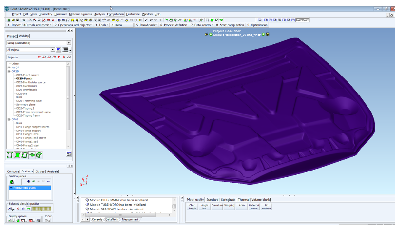

🔳 Interface Layout

The PAM-STAMP GUI is designed with productivity in mind. It includes:

  • A main menu bar
  • Horizontal toolbars docked at the top
  • Vertical toolbars on the left/right
  • An output window at the bottom
  • A custom command bar
  • Optional multi-function toolbars

👉 All these bars can be customized, moved, hidden, or rearranged however you want.

💡 There’s also a full tutorial and training course on GUI usage, available via myESI.


🧱 3D Model Display in Viewer

In the 3D View:

  • You can pan, zoom, rotate, and fully navigate models
  • You can use shortcuts for faster access to commands

✅ Some of the important shortcut keys are shown in the figure below:


🛠️ GUI Toolbars – Complete Toolbar System


🔧 Show/Hide Toolbars

Right-click on the toolbar area to show a full list of available toolbars. These are split between:

  • Standard toolbars
  • Enhanced toolbars (shown below the horizontal line in the list)

You can also dock/undock or move them around to suit your workflow.


Here are the key predefined toolbars you’ll likely use the most:

1. Standard Preprocessing Toolbar

All essential functions for simulation setup.

2. Check Toolbar

For visualizing:

  • Mesh edges
  • Tool distances
  • Element normals
  • Free CAD edges
  • Small cracks (shown via annotations)

3. Postprocessing Toolbar

All tools needed to analyze simulation results.


🧩 More Predefined Toolbar Details

  • You can enable text labels on toolbars
  • Toolbars with icons + text can help new users learn faster
  • Toolbar layout and content can be fully customized

📷 Standard Toolbar Tools

Includes:

  • Zoom controls
  • View from z-direction
  • Window zoom
  • Center of rotation
  • Multi-window sync
  • Camera rotation
  • Display edges
  • Shadow toggle
  • Crosshair cursor

🧭 Views Toolbar

  • Choose from preset 3D views
  • Define your own views and save them
  • Stored views are saved in your .psp project file

🧪 Check Toolbar Tools

  • Show free or double element edges
  • Show free CAD edges
  • Show element normals
  • Detect cracks or small discontinuities

🎞️ Animation Toolbar

Control the simulation playback:

  • Navigate between time steps
  • Change playback speed
  • Load/unload specific steps

🎯 Selection & Annotation Toolbars

Add rich visuals to your model:

  • Captions (text, arrows, circles)
  • Result values (max, min, etc.)
  • Change font size
  • Captions move with model
  • Use multiple annotation layers

📏 Measure Toolbar

You can:

  • Measure distances, path lengths, radii, and angles
  • Measure radius from a 2D cross-section
  • Measure undercut angles vs Z-direction
  • Get instant object info (dimensions, coordinates)

🧠 Enhanced Toolbars and Custom Options

You can create customized toolbars for specific tasks.

🧮 Workflow Toolbar Example

There’s a default workflow toolbar delivered with PAM-STAMP V2015.1:

  • Helps define single/double action processes
  • Docked horizontally for quick access

🎨 GUI Customization – Make It Yours


⚙️ What You Can Customize:

  • Toolbars
  • Menu bars
  • Command macros
  • Keyboard shortcuts
  • Themes and GUI layout
  • File paths
  • Default parameters

All these are stored in configuration (.cfg) files, located in:

  • C:\Documents and Settings\<user> (Windows)
  • /usr/local/<user> (Unix)

These can be:

  • Local (per-user)
  • Global (for company-wide setups)

⚠️ Personal .cfg settings override installation defaults!


🗂️ Where to Access It

Go to:
Right-click toolbar area > Customize, or
Main menu > View > Toolbars > Customize


🔒 Macro & Advanced Mode

The Stamp Tool Kit (macro generator) is only visible in Advanced User Mode, which is now active by default since version 2015.1.

✅ Status is shown at the bottom right corner of the GUI.


🧾 Configuration Tabs

In the “Customize > Options” window, you can define settings for:

  • Design – Set default PAM-TUBEMAKER values
  • DeltaMESH – Import, join, remesh defaults
  • Process – Units, solver checks, blank/tool order
  • Files – Set import/export paths and solver host
  • GUI – Undo, camera, annotation radius
  • Geometry – Mesh orientation, offset values
  • Contours – FLD settings, max angle on solids
  • Tool Editor – Default flanging values and mesh size
  • Macros – Default process macro options
  • Roll Hemming – Roll-hemming specific options

✨ One-Click Commands & External Tools

  • You can create custom commands to chain actions
  • Add external tools like spreadsheets, renderers, or calculators directly into the GUI

🧱 Miscellaneous – Extra Productivity Tips


🔀 Right-Click Power

  • Right-click main screen = access global commands
  • Right-click object tree = get object-specific tools

🆘 Press F1 for quick help any time.

📁 Files in PAM-STAMP – What They Are, What They Do

PAM-STAMP uses a wide range of file types to store your simulation data, material information, macro setups, meshes, solver input/output, and more. These files can be binary or ASCII (text-editable) and are often project-specific.

Let’s break them all down, starting with the most common file types.


📝 ASCII Input – .att File

🔎 What is It?

  • The .att file (Attribute file) is an ASCII file that holds your multistage simulation setup.
  • It includes all simulation parameters, one after the other.
  • It’s a text version of your .pre file — great for tweaking things manually or programmatically.

🛠️ How It’s Created

  • By default, when you start a simulation, PAM-STAMP writes the .att file automatically.
  • You can also choose “Write input file only” (without starting the simulation) from the GUI.

🔄 Simulation Behavior

  • If both .pre and .att files exist in the project folder, the .att file takes priority — its data overrides .pre.
  • You can modify .att, reopen the project, and save — PAM-STAMP updates .pre accordingly.

🧩 Mesh Input – .mif File

The .mif file is an ASCII mesh input file used to represent all the mesh data for the solver.


✨ What’s Inside?

  • Node and element data
  • Curves and objects
  • Restart info
  • Everything needed to run a simulation

You can export it via Export Mesh > .mif format in the GUI.


🔧 Special Notes:

  • Starts with DEF_ section headers
  • Each section defines parameters and entities
  • Supports comments (start with #)
  • Lines can’t exceed 256 characters

📝 You can even export .mif from a .res (result) file, not just .pre.


🚀 Running a Simulation with .mif

To use .mif instead of .pre:

  1. Modify the .att file
  2. Add this section:
txtCopyEditDEF_MODEL_INPUT_FILE  
FILENAME = 'yourfilename.mif'

Then start the simulation normally.


🧾 File Type Glossary – Full List of Project File Types

Here’s a complete breakdown of PAM-STAMP’s files. Prefix gn = project name.

📦 Material Database

  • material.psm – One ASCII file per material

⚙️ Process Macros

  • macro.ksa – AUTOSTAMP standard macro
  • macro.ktf – Tube hydroforming macro
  • macro.ktb – Tube bending macro
  • macro.ksi – INVERSE macro
  • macro.kti – INVERSE tube bending macro
    (All are ASCII files)

📁 Project Core Files

  • gn.psp – Shared data across modules
  • gn.pre – Project setup + mesh (binary, multistage)
  • gn.att – Setup (ASCII version of .pre)
  • gn.mif – Mesh file (ASCII)
  • gn.i.und – Undo history (temporary)

🧱 CAD Meshing Module

  • gn.I.msh – Mesh data for module
  • gn.I.cmd – DeltaMESH command file
  • gn.Ir.dtc – DeltaMESH data after import
  • gn.Ia.dtc – After joining
  • gn.Im.dtc – After meshing
  • gn.Im.fma – Temporary ASCII mesh result
  • gn.I.his – DeltaMESH messages

🛠️ Design Module – PAM-TUBEMAKER

  • gn.J.add – Model definitions (mesh, profiles)
  • gn.J.trm – Die trimming definition
  • gn.J.ptl – User-defined PTL
  • gn.bending – Bending data
    (All ASCII or binary depending on usage)

🧲 Die Compensation

  • Gn_Outifo.input, .lis, .output, .history, .results – All ASCII, used by the Outifo solver for compensation

🧮 Linear Solver

  • Gn_linear.asc, Gn_linear_depla.asc, Linearsolver.LOG – Input/output for linear calculation

📦 Substructure Data

  • Gn.ini – Node and center-of-gravity data
  • Gn.S0i – Displacement data per stage
  • Gn_ids.bf – Node mapping (main ↔ subrun)

🔁 Solver Restart

  • gn.irs – Restart input file
  • gn.[i].rst – i-th restart file (binary)
  • gn.[i].rst_P – Restart file per processor node

⚠️ PAM-STAMP will overwrite oldest files when max restart files are exceeded.


📉 Post-Processing

  • gn.[i].res – i-th result state
  • gn.end.res – Final result state
  • gn.his – History curve data
  • gn.out – Solver log
  • gn.err – Solver error log
  • gn.msg – Solver messages
  • gn.qst, gn.asw – Solver request-response files
  • gn_M01 – Mapping results
  • gn.pda – Post-process archive
  • gn*.rib – Renderer files

🗃️ Archive Components

Archiving a project usually includes:

  • gn.pre, gn.psp, gn.end.res, gn.his, gn.out, gn.err, gn.msg
  • And for modules: gn.I.msh, gn.J.msh, gn.J.add, gn.1.res, gn.pda, etc.

⚙️ Solver Manager – Setup, Configuration & Startup

The Solver Manager is a background service (also called a daemon) that runs on your simulation host. Its main job is to:

  • Listen for simulation requests sent from PAM-STAMP GUIs
  • Launch and manage solver processes
  • Coordinate everything whether you’re working on local or remote machines

It’s delivered as a single executable file (typically called solvermanager.exe), and is included in the standard PAM-STAMP installation.


🔧 How to Configure the Solver Manager

You can configure it in two ways:

  1. By command-line arguments
  2. By editing a configuration file

🔺 If you’re on Windows and using it as a service, you can only set the log file path via command-line. All other options must go in the config file.


📄 Location of the Config File

The solver manager looks for its settings in:

  • The config file path specified by -config
    or
  • A default file named solvermanager.exe.cfg (must be in the same directory as the executable)

🛠️ How to Generate a Default Config File

Use this command:

bashCopyEditsolvermanager.exe -genconfig [-config <filename>]

This generates a default config file (solvermanager.exe.cfg) with all available options commented out. To activate an option:

  • Remove the # at the beginning of the line
  • Edit the value after the | symbol

🧾 Configuration Options

🔹 Server Parameters

OptionWhat it does
SERVER_PORTPort used to listen to GUI requests (default = 1201)
SERVER_PROTOCOL_VERSIONCommunication version with GUIs
SERVER_LOG_FILEPath to the log file where messages are written

🔹 Solver Launching

OptionWhat it does
SCRIPT_TEMPLATEPath to a custom launch script template
BATCH_COMMANDCommand to run solvers in batch mode (default: batch)
LIBRARY_PATHSets library paths like /usr/lib
LIBRARY_VARIABLESets environment variable name for library path
MP_VARIABLEMulti-processor environment variable (e.g., number of threads)

🔹 Misc Settings

OptionFunction
TEMP_DIRECTORYWhere temporary scripts are stored (default: /usr/tmp)
SAVE_LAUNCH_SCRIPTIf YES, saves the generated script (default: NO)
SOURCE_PROFILEEnables use of user .profile scripts
FORCE_AUTOMOUNTTriggers mounting of remote dirs (if needed)
SCRIPT_CLEANUP_DELAYWait time before deleting launch script

📑 Example of a Launch Script Template

This only applies to Unix/Linux systems. The template includes replaceable keywords like:

  • $PAMPARAM_WORKDIR – simulation work directory
  • $PAMPARAM_CMDLINE – full command to launch solver
  • $PAMPARAM_OUTPUT – file where output is stored

These are auto-filled during execution.


🚀 Starting the Solver Manager

🖥️ On Unix/Linux:

Open terminal and run:

bashCopyEditcd <solver manager folder>
nohup solvermanager.exe [-output /your/log/path] > /dev/null &

To start it at boot:

  • Add the command to the system’s daemon/startup scripts.

🪟 On Windows:

To run manually:

cmdCopyEditcd <solver manager folder>
solvermanager.exe -noservice -output <log path>

⚠️ Note: If you run it like this, simulations are tied to your Windows session and stop when you log out.


To run as a Windows Service:

  1. Create a user account (e.g., pamservice) with “log on as service” rights.
  2. Run this:
cmdCopyEditsolvermanager.exe -service -user pamservice
  1. Enter the password when prompted.

✔️ This keeps solver processes alive even after logout.

Leave a Reply

Discover more from Technical Gamer

Subscribe now to keep reading and get access to the full archive.

Continue reading